
Creating a basic AWS network with Terraform
by Darren Murphy
Amazon Web Services (AWS) offers a wide range of cloud computing services, one of which is networking. In this post, I’ll go over the fundamentals of setting up a basic but robust and scalable network infrastructure using AWS and Terraform.
To begin I’ll cover the creation of a single Virtual Private Cloud (VPC), configuration of multiple Availability Zones (AZs), setting up public and private subnets, in a single region, I’ll then look at adding an Internet Gateway, and Network Address Translation (NAT) Gateways.
- AWS Networking: An Overview
- Why Deploy Multiple AZs, Public and Private Subnets?
- Terraform project structure
- Walkthrough: Creating and Managing AWS Network with Terraform
- Gateways
- Route tables
- Conclusion
AWS Networking: An Overview
AWS provides scalable and highly reliable networking services which allow businesses to design and implement a network infrastructure meeting their specific requirements. Core components of AWS networking include:
-
AWS Account: is an Amazon Web Services identity that you use to log in and access AWS services. Each AWS account has its own resources, separate from other accounts, and its own limits on each AWS service. It is essentially your own workspace within the vast expanse of AWS cloud services.
-
AWS Region: is a physical location around the world where AWS clusters data centers. Each AWS Region is designed to be isolated from the other AWS Regions. This achieves the greatest possible fault tolerance and stability.- VPC: Virtual Private Cloud allows you to provision a logically isolated section of the AWS Cloud where you can launch AWS resources in a virtual network defined by you.
-
Subnets: A subnet is a range of IP addresses in your VPC. You can launch AWS resources into a subnet that you select.
-
Availability Zones (AZs): AZs are essentially isolated and physically separate locations within regions from which cloud services originate and operate. They are physically separated within a geographic region and are designed to minimize failures. With multiple AZs, your resources can remain resilient against potential outages.
-
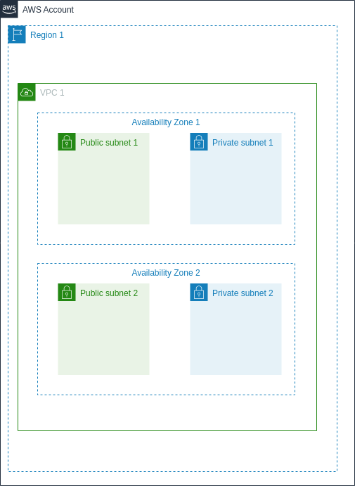
The following diagram gives an overview of these components and their relation to each other
Why Deploy Multiple AZs, Public and Private Subnets?
The deployment of multiple AZs and the differentiation of public and private subnets within your VPC allows you to increase availability, fault tolerance, and scalability of your applications.
-
Multiple AZs: By deploying your resources across multiple AZs, you can ensure high availability and fault tolerance. If one AZ becomes unavailable, traffic can be directed to resources in another, ensuring your applications remain up and running.
-
Public and Private Subnets: This design provides an extra layer of security by limiting the exposure of your resources. Resources that must be publicly accessible are placed in a public subnet with routes to the Internet Gateway. Those that don’t require internet access are placed in a private subnet, improving security.
Terraform project structure
I’ll be using my standard approach to structuring the terraform project, with individual files for specific functions and separate vars files per environment, read more about that here
-
Terraform state
- I’ll be storing my state file in AWS S3 as described here
Walkthrough: Creating and Managing AWS Network with Terraform
All of the code used here can be found in this Github repo
Now, let’s dive into setting up an AWS network with Terraform. I’m assuming you’ve set up Terraform on your host and have authentication setup and your host is able to authenticate to the AWS service. If not check out this post first here
starting with a new directory called aws-terraform-networking let’s get the main.tf file setup first of all, setting the backend and required providers.
terraform {
# configure the backend for remote state file storage
  backend "s3" {}

  required_providers {
      aws = {
        source  = "hashicorp/aws"
        version = "~> 4.0"
    }
  }
}

# Required provider
provider "aws" {
  region = var.region
}
The next step is to create files for the networking components, I’m going to break these out into vpc.tf and subnets.tf we’re also going to tokenise the code so that we can define environment specific variables and use the same code for multiple deployments. So we’ll also need to create a variables.tf file and an enviroment specific .tfvars file for each environment
firstly the vpc.tf
# Creating a VPC
resource "aws_vpc" "vpc_1" {
  cidr_block = var.vpc_cidr
}
and the the subnets.tf
# Creating public subnets
resource "aws_subnet" "public_1" {
  vpc_id     = aws_vpc.vpc_1.id
  cidr_block = var.public_subnet_1
  availability_zone = "${var.region}${var.az_1}"
}

resource "aws_subnet" "public_2" {
  vpc_id     = aws_vpc.vpc_1.id
  cidr_block = var.public_subnet_2
  availability_zone = "${var.region}${var.az_2}"
}

# Creating private subnets
resource "aws_subnet" "private_1" {
  vpc_id     = aws_vpc.vpc_1.id
  cidr_block = var.private_subnet_1
  availability_zone = "${var.region}${var.az_1}"
}

resource "aws_subnet" "private_2" {
  vpc_id     = aws_vpc.vpc_1.id
  cidr_block = var.private_subnet_2
  availability_zone = "${var.region}${var.az_2}"
}
Note in order to concatenate two variables together we need to use the interpolation syntax in the form "${var1}${var2}"
We’ll now need to create a variables file variables.tf where we’ll define the variable keys, but we’ll leave the values blank here, they’ll be defined after in the environment specific .tfvars file
variable region {}

variable s3_bucket {}

variable s3_key {}

variable vpc_cidr {}

variable public_subnet_1 {}

variable public_subnet_2 {}

variable private_subnet_1 {}

variable private_subnet_2 {}

variable az_1 {
  default = "a"
}

variable az_2 {
  default = "b"
}
Note that the az variables have a default value assigned, for the most part these will be the same for every deployment, but we still have the flexibility to use different AZ’s in a specific deployment (AZ’s b& c for example) by setting the variable in the .tfvars file which will then take precedence.
Next, the environment specific .tfvars file, for the purpose of this post I’ll create this in environments\eu-west-1\dev.tfvars
region = "eu-west-1"

s3_bucket = "terraform-state-smurphin"

s3_key = "aws-networking"

vpc_cidr = "10.10.0.0/16"

public_subnet_1 = "10.10.1.0/24"

public_subnet_2 = "10.10.2.0/24"

private_subnet_1 = "10.10.255.0/24"

private_subnet_2 = "10.10.254.0/24"
As we’ll be using the default AZ’s inherited from the variables.tf file, there’s no need to set them explicitly here.
State file configuration
- We’ll also need to specify the settings for the S3 backend for this environment which will be done in this file
environments\eu-west-1\dev.tfbackend
  bucket = "terraform-state-smurphin"
  key = "aws-networking-dev"
  region = "eu-west-1"
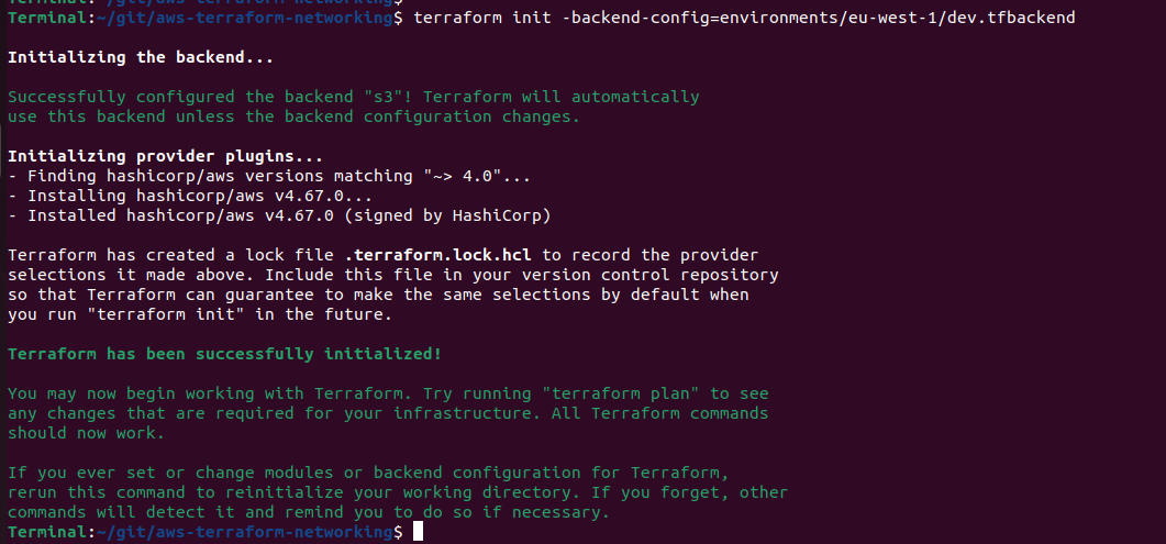
- Now you have all that in place we can initialise the repository for Terraform to start managing it, we’ll need to specify the variables we’ll use for the backend as well, using this command will work for this example;
terraform init -backend-config=environments/eu-west-1/dev.tfbackend
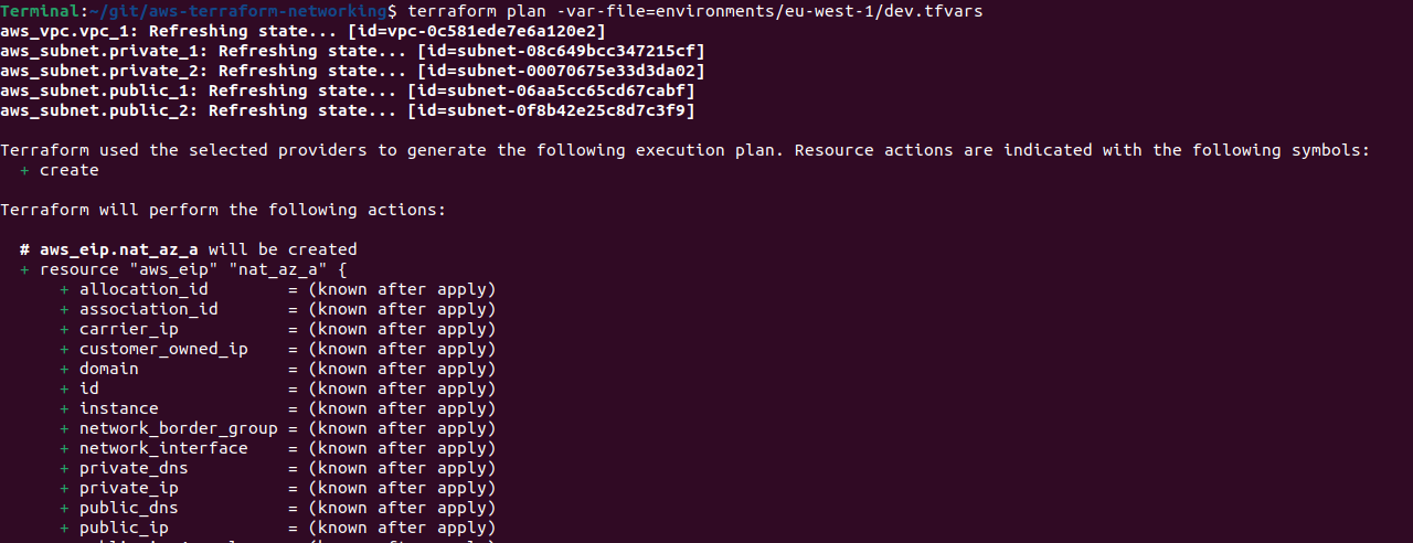
Once the repo is initialised we’re ready to start deploying our infrastructure, first we can run a terraform-plan to make sure it’s going to do what we expect, remembering to pass the environment specific variables file.
terraform plan -var-file=environments/eu-west-1/dev.tfvars
That should give us an output similar to the below
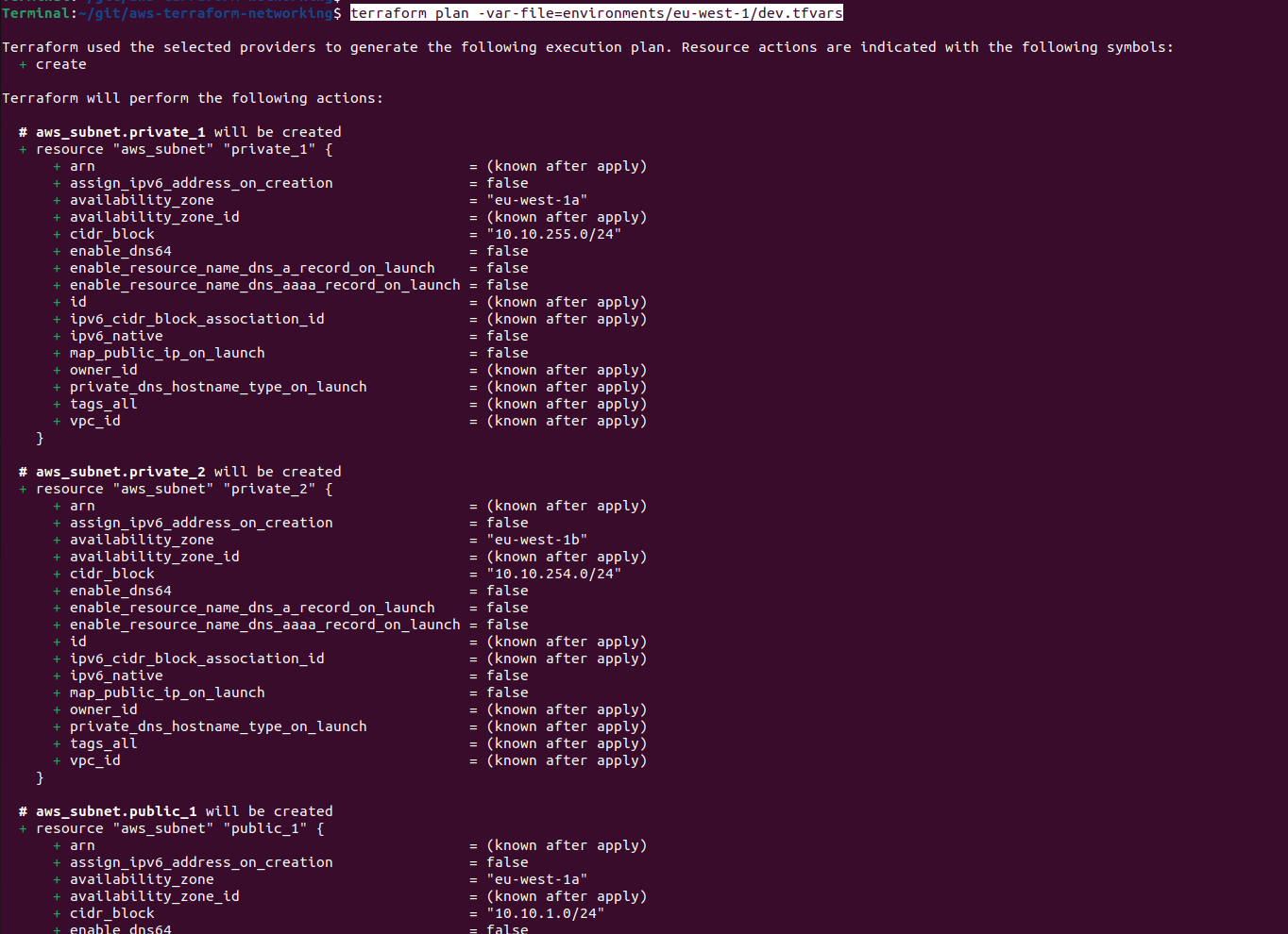
It looks like everything is ready to go! We can now deploy the code with terraform-apply
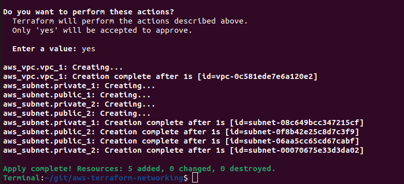
terraform apply -var-file=environments/eu-west-1/dev.tfvars
You’ll be shown the details again of what Terraform will deploy and be prompted to confirm the actions, if all looks good type yes and watch as Terraform deploys your network infrastructure in a matter of seconds.
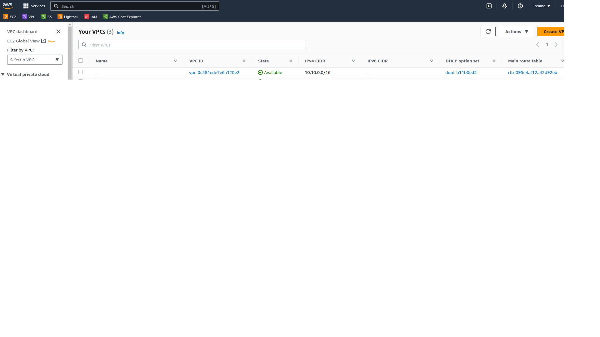
We can go over to the Amazon console and confirm that the resources have actually been deployed.
we see our new VPC
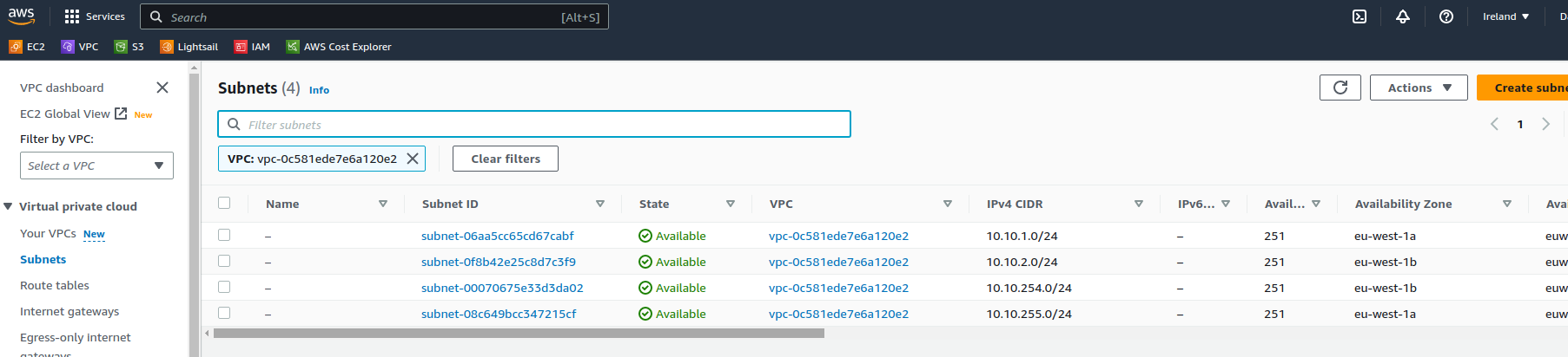
Our new subnets have been configured across 2 availability zones
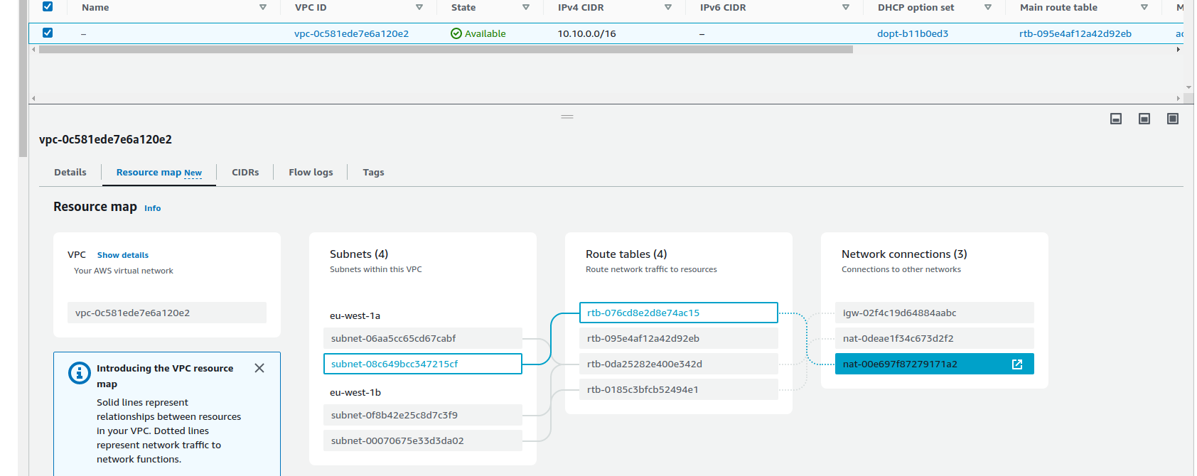
And if we look at the resource map we can see how these tie together
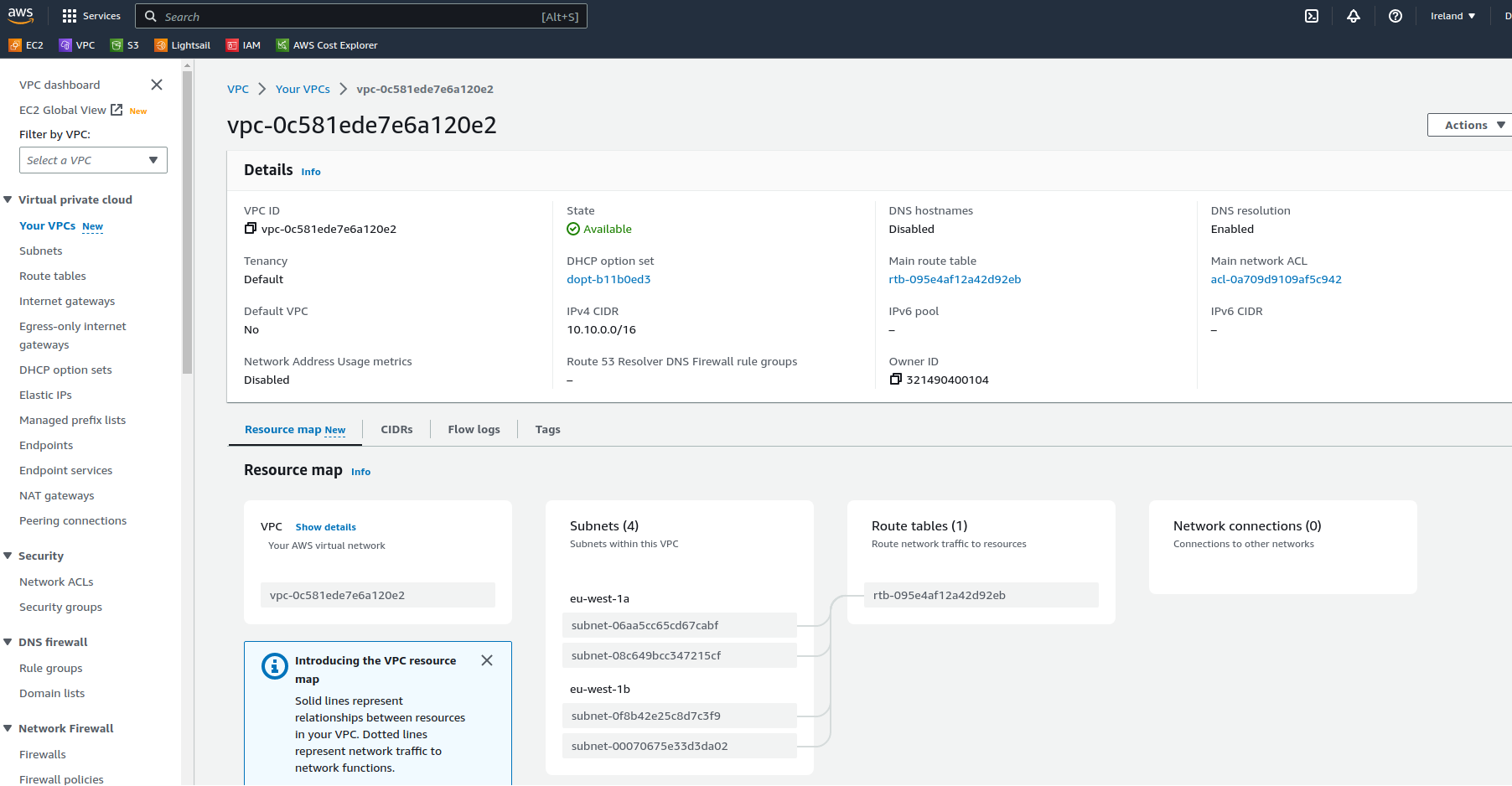
Note that all subnets are currently associated with the default route table for this VPC (created automatically) this means that functionally all subnets act the same , whether intended to be private or public. I’ll go over that in more detail below
This is a basic network setup, if it had some workloads running in one of the subnets, they would be able to communicate with instances in any of the other subnets within the VPC.
It’s important to note, within a VPC it’s possible to route between any of the subnets, public and private are just logical concepts and are only relevant for connections from outside the VPC, if you wish to restrict traffic flow between subnets within the VPC then security policies need to be used.
Now we have the basic components in place we need to connect them to the world outside of the VPC, either the internet or other VPCs, AWS accounts, physical data centres etc. For this post I’m going to focus on creating internet connectivity and I’ll build on the other types of connectivity in separate posts.
We need to add some additional components to our Infrastructure to provide connectivity outside of the VPC
Gateways
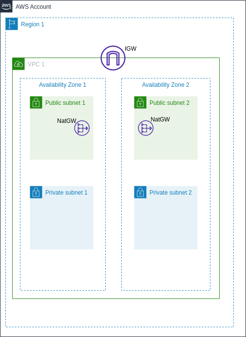
- Internet Gateways: An Internet Gateway is a horizontally scalable, redundant, and highly available VPC component that allows communication between instances in your VPC and the internet.
- NAT Gateways: A NAT Gateway enables instances in a private subnet to connect to the internet or other AWS services but prevents the internet from initiating a connection with those instances. The NAT Gateway is deployed into the public subnet with an Elastic IP and the route table of the provate subnet will send internet bound traffic via the Nat Gateway. One Nat Gateway per availability zone should be deployed for resiliency.
our network topology will look like the below
we’ll create a gateways.tf file to look after those components
# Creating an Internet Gateway and attaching it to the VPC
resource "aws_internet_gateway" "igw" {
  vpc_id = aws_vpc.vpc_1.id
}

# Creating NAT Gateways
resource "aws_nat_gateway" "nat_gw_az_a" {
  subnet_id     = aws_subnet.public_1.id
  allocation_id = aws_eip.nat_az_a.id
}

resource "aws_nat_gateway" "nat_gw_az_b" {
  subnet_id     = aws_subnet.public_2.id
  allocation_id = aws_eip.nat_az_b.id
}
we’ll also need Elastic IPs to associate with the Nat GWs, we’ll create those in elastic_ips.tf
#Allocate Elastic IPs for the Nat Gateways to use
resource "aws_eip" "nat_az_a" {
  vpc = true
}

resource "aws_eip" "nat_az_b" {
  vpc = true
}
Route tables
Finally we’ll need to tell our instances how to route to their destinations, as well as preventing inbound internet connectivity to the private subnets.
Route Tables: are used to direct network traffic within your VPC. Each subnet in your VPC is associated with a route table that controls its traffic flow. Route tables consist of routes that dictate where the traffic from your subnet is directed. For instance, if instances in a subnet need to access the internet, a route pointing all traffic (0.0.0.0/0) to an internet gateway can be added to the route table.
Route tables can be shared by multiple subnets if the routing policy is the same, so for our use case we only need a single public route table, but two private route tables as their destinations will be different NAT Gateways in order to maximise resiliency, we’ll manage these in route_tables.tf
# Creating a route table for the public subnet
resource "aws_route_table" "public" {
  vpc_id = aws_vpc.vpc_1.id
  route {
    cidr_block = "0.0.0.0/0"
    gateway_id = aws_internet_gateway.igw.id
  }
}

# Creating a route table for the private subnet
resource "aws_route_table" "private_1" {
  vpc_id = aws_vpc.vpc_1.id
  route {
    cidr_block = "0.0.0.0/0"
    nat_gateway_id = aws_nat_gateway.nat_gw_az_a.id
  }
}

resource "aws_route_table" "private_2" {
  vpc_id = aws_vpc.vpc_1.id
  route {
    cidr_block = "0.0.0.0/0"
    nat_gateway_id = aws_nat_gateway.nat_gw_az_b.id
  }
}

# Associating the public subnets with their route table
resource "aws_route_table_association" "public_1" {
  subnet_id      = aws_subnet.public_1.id
  route_table_id = aws_route_table.public.id
}

resource "aws_route_table_association" "public_2" {
  subnet_id      = aws_subnet.public_2.id
  route_table_id = aws_route_table.public.id
}

# Associating the private subnets with their route tables
resource "aws_route_table_association" "private_1" {
  subnet_id      = aws_subnet.private_1.id
  route_table_id = aws_route_table.private_1.id
}

resource "aws_route_table_association" "private_2" {
  subnet_id      = aws_subnet.private_2.id
  route_table_id = aws_route_table.private_2.id
}
Now we’re ready to run a plan and make sure everything looks ready to go
terraform plan -var-file=environments/eu-west-1/dev.tfvars
All looks good, so I’ll go ahead and apply
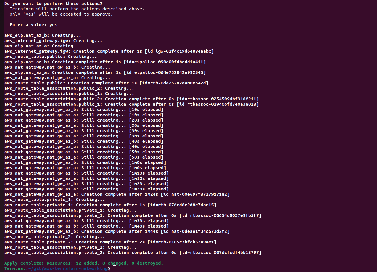
terraform apply -var-file=environments/eu-west-1/dev.tfvars
And after a minute or two we now have 12 new resources deployed and associated correctly.
If we take a look in the AWS console we can also see all of the resources deployed in the VPC, and even see how they are associated with each other.
Conclusion
AWS networking is a vast and powerful domain that enables businesses to tailor network infrastructure to their specific needs. The combination of multiple AZs and the use of public and private subnets allows for a resilient, secure, and scalable infrastructure. Using Terraform this can be very simple to setup and manage, as well as replicate to other environments, ensuring that deployments are always consistent.
I hope this post has helped you understand how to set up an AWS network using Terraform.
In some future posts I’ll build on this basic network and add some extra components, connecting to multiple VPCs, multi Region deployments etc.
Happy terraforming!
tags: AWS - Networking - IaC - Infrastructure - Terraform